1. Verifying Load Cell Connections with a Multimeter
After wiring a load cell, have you ever wanted to check that the connections are correct?
You can easily check load cell wiring with a digital multimeter. The following diagram shows where to measure when a single load cell is connected to an indicator. When a summing box is used to connect multiple load cells, similar measurements can be made using the terminal blocks inside the summing box.
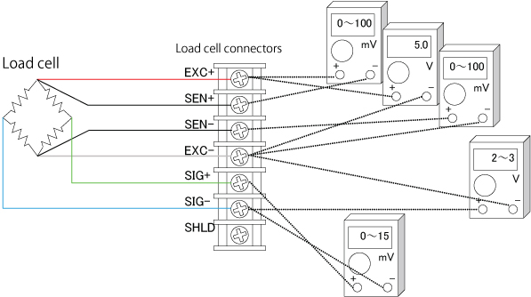
Measurement Locations to Check Load Cell Connections
Measurements to Check Load Cell Connections
| Measurement point | Measurement content | Remarks | |
| EXC+ | SEN+ | Voltage drop on the EXC+ side of the load cell cable | Usually less than 100 mV, but may exceed 1 V with extremely long load cell cables. In 4-wire systems, nothing is connected to SEN+, so it should read 0 V. |
| EXC+ | EXC- | Excitation voltage applied to the load cell | Depends on the weighing indicator model; typically 5 V or 10 V. Please check the specifications of your indicator. |
| SEN- | EXC- | Voltage drop on the EXC- side of the load cell cable | Similar value to the EXC+ – SEN+ measurement. |
| SIG- | EXC- | Midpoint voltage of the load cell | Approximately half of the excitation voltage. |
| SIG+ | SIG- | Output voltage of the load cell | Compare with theoretical values based on rated capacity, actual load, and excitation voltage. For 5 V excitation: 0–15 mV; for 10 V excitation: 0–30 mV is typical. |
Moreover, many of our weighing indicators feature a check mode that allows you to directly read the load cell output in mV/V (millivolts per volt).
The photo below shows the AD-4411 weighing indicator in check mode, displaying a load cell output of 0.18432 mV/V—all without the need for any specialized measuring equipment.
This kind of high-sensitivity and high-resolution measurement is extremely difficult to achieve with a standard digital multimeter. The check mode provides a simple yet powerful way to verify load cell performance with precision.
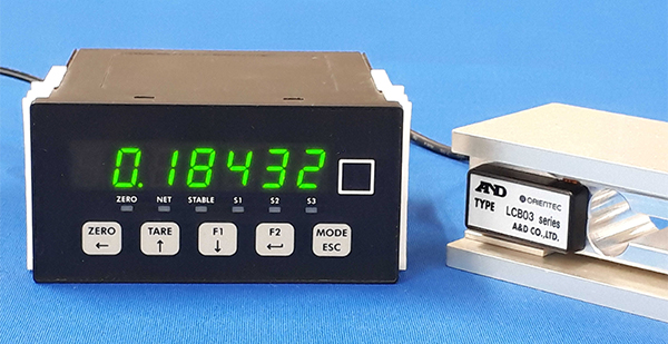
In the photo, a 3 kg-rated load cell is connected. The indicator is so sensitive that even blowing air onto the load cell causes a noticeable change in the displayed value.
This demonstrates that even load cells rated for tens of tons can be tested by simply pushing or pulling by hand to confirm their operation.
Additionally, if the polarity of the load cell wiring is reversed, the display value will decrease as load is applied.
In cases where a load cell has been damaged by overload, the check mode can reveal a significant zero-point deviation, even when no load is applied.
As you can see, mV/V display mode offers a wide range of practical diagnostic uses, making it an invaluable tool for troubleshooting and setup.
2. The Hidden Risk of Using Incorrect Crimp Terminals
One day, a customer called and said, “I’ve bought a lot of A&D load cells, and the indicator value varies just by touching the load cell cable on several of them”. We carefully inspect the operation of our load cells before we ship them, so we doubted that there could be that many defective items in one place.
We asked the customer how the indicators were being used. Even after extensive questioning, we couldn’t determine the cause of the problem, so we asked one of our service engineers to go and check things out.
The service engineer reported that, “The indicator value definitely changes just by touching the cable. What’s surprising is that it doesn’t seem to happen when you touch far away from the terminal”.
“When the load cell is connected to the terminal directly without using a crimp-on terminal, it’s fine,” he continued. “It’s weird. The crimp-on terminal shouldn’t affect the indicator value…”
After a little more investigation, we finally found out what the problem was. The crimp-on terminals being used didn’t match the thickness of the conductor of the load cell cables. That’s why touching the cable changed the contact resistance and negatively affected the indicator value. If the contact resistance of the EXC terminal applying power to the load cell increases, the sensitivity of the load cell drops similarly.
The input resistance of many load cells is 350Ω. Even if the contact resistance increases by a mere 35 mΩ- or 1/10,000th - the load cell output drops by 1/10,000th. This shows why it’s dangerous to use ill-fitting crimp-on terminals like this.
When troubleshooting in the field, it’s important to get the correct information right from the start. However, the cable size of the crimp-on terminal wasn’t one of the first things to come to mind, and we wasted a lot of time solving this problem.
Crimp-on terminals can be convenient for making stable connections. However, if they are used incorrectly, things such as the oxidation of metal surfaces can cause unexpected problems, even after years of trouble-free use.
There are many types of crimp-on terminals with different shapes and hole diameters to suit connection cables. Be sure to choose crimp-on terminals that are suitable for your cables and use appropriate crimping tools.
3. Do You Need Recalibration After Changing Indicator Settings?
We often get questions like, “I’ve made a scale by combining a load cell and an indicator. I have to increase the capacity of the scale and want to change the capacity setting of the indicator. If I do that, do I have to recalibrate it?” We probably get this type of question a lot because of the difficulty of placing counterweights with large silos and automatic scales.
In such cases, recalibration is probably not necessary. Increasing the capacity by a few percent won’t cause many problems even if a recalibration is not performed. Since the linearity of the indicator and load cell is sufficient, changing the capacity by a few percent won’t cause much error.
Furthermore, weighing indicators are calibrated using an internal resolution that is finer than the displayed resolution, and this data is stored in nonvolatile memory. As a result, the zero point and span remain the same even if the minimum scale value is subsequently changed.
Nevertheless, it’s better to recalibrate when changes have been made to the scale. Furthermore, it’s important to make sure that insufficient mechanical strength or other issues do not cause problems when increasing the capacity setting.